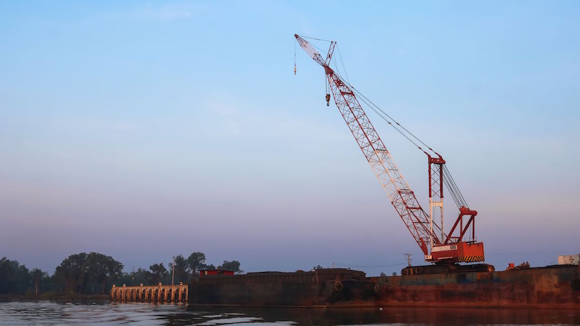
Working machines like mobile cranes are designed to hoist and move heavy loads. Despite their sturdiness, cranes do have an upper limit of how much weight they can handle. That’s where force measurement comes in. For cranes without hydraulics, tension links measure the strain on their cabling systems to make sure overloading does not occur.
Mobile cranes are ubiquitous in shipyards, construction sites, and other industrial locations, lifting and transferring thousands of pounds at a time. But their lifting capacity is not unlimited. If a crane hoists more than what it’s designed for, the mobile machine can weaken, bend, tip over, and even collapse – endangering people and property.
For cranes that lift using cables rather than hydraulics, tension links are commonly used force measurement transducers that prevent overloading.
How Do Tension Links Work?
Tension links come in several shapes, sizes, and configurations, but the majority have two bore holes. Cables pass through and exert force on these holes. To calculate how much tension the cables are under, the measuring body uses the Finite Element Method (F.E.M.). This is a type of calculation that breaks down complex system into simpler components called finite elements. The measuring body analyzes each finite element using differential equations, and the aggregate result enables an accurate prediction of how many kN of force the entire system is currently withstanding.
A crucial element of this force measurement transducer is the strain gauge bridge circuit, a tiny thin-film sensor placed directly in a small opening along the tension link load cell’s longitudinal axis that registers tensile or compressive force.
A strain gauge is made of very thin wire or foil arranged in a grid pattern. These metal components experience a change in electrical resistance when its shape is deformed. An amplifier, with voltage or current output, is calibrated to produce a known output with the change in force. In a balanced state, the voltmeter reading in the strain gauge bridge circuit will be zero. In the presence of a load, the strain gauge stretches, causing a linear increase in electrical resistance that leads to a corresponding change in voltage. This change is used to determine the tensile force in the cables.
Advantage of Tension Links for Force Measurement
Tension links are extremely user-friendly. Because they can accept shackles on both ends, these force measurement devices are easy to install inline between the dead end/padeye and the end of the cable where users want to measure the tension.
For additional safety, WIKA’s tension links place two measuring systems in one very small space. Two strain gauge bridges are vapor-deposited onto one sensor element, which is then welded into the deformation body. This redundancy allows users to easily upgrade to a two-channel sensor technology to fulfill EN13849 or other safety standards without changing the external geometry of the tension link.
Tension Links by WIKA
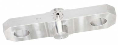
Redundant stainless steel tension link, model F73C1
WIKA’s broad range of force solutions includes the F73 series, ideal for dynamic and static force measurement. These tension links are made of either high-strength, fine-grained structural steels featuring top-quality surface protection, or corrosion-resistant stainless steels. Thanks to quality materials and careful engineering, the F73 series can withstand high shock and vibration conditions, offering long-term stability and excellent reproducibility.
For assistance in finding the right devices for your specific applications, contact our experts in force measurement and mobile working machines.
Products in this post: |
thanks for info