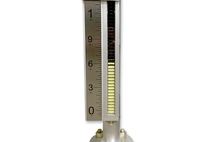
Consistent and reliable, magnetic level indicators are widely used in many sectors, including the petrochemical industry. The operation of these cost-effective instruments is simple and elegant: A float resides within a chamber that, most commonly, is attached to the side of a tank or vessel via piping. Inside the float is a magnet assembly.
A magnetically affected visual indicator is attached to the outside of the float chamber. As the liquid level within the tank – and thus the chamber – increases or decreases, the float rises or falls with it. Magnetic wafers or flags on the indicator react with the magnet assembly within the float, giving users an accurate reading of the liquid level. Because the process liquid is completely sealed in the chamber of this instrument, the dangers and maintenance headaches associated with glass reflex or transparent gauges is eliminated.
A glass gauge fits into a specific application with the use of various pipes, nipples, fittings, and so on. The piping allows the process to connect to the gauge from the back or from the top and bottom of the gauge. Magnetic level indicators, however, often are not exact replacements for glass gauges due to their floats – the heart of the instrument. The float must be designed for the process condition to take into account the individual application’s pressure, temperature, and specific gravity. In order to be buoyant in virtually any liquid, it must contain a corresponding amount of volume. In short, for the float to work properly, its size varies depending on the liquid. Sometimes a float is 6 inches long, but in rare instances it can be more than 30 inches long! The magnet inside the float is usually located about 2 inches from the top of the float. This leaves the balance of the length of the float, creating wasted space. The pipe chamber obviously must contain the entire float, so it has to be designed and manufactured to accommodate this additional length.
Like glass gauges, magnetic level indicators can be attached to a process vessel with a variety of connection options. Most common for both types of visual indicators is from the side, but in some instances these instruments are connected from the top and bottom of the chamber, with no side connections at all. This is where we run into problems when replacing glass gauges. Existing piping may have been designed precisely for the size of a glass gauge. Although a magnetic level indicator is a desirable replacement, the additional space needed to encompass the float makes some retrofits impossible. It’s little wonder that when customers are ready to update their technology, some fear the plumbing headache that may come with magnetic level indicators.
Real-life problem – real-life solution
Engineers at a major petrochemical company faced this problem when trying to replace a faulty glass reflex gauge with a safer and more reliable magnetic level indicator. With this replacement, they could also improve the visibility of the level of liquid propane and butane in their vapor knockout pots. The existing piping to the glass gauge allowed for connections directly on the top and bottom of this instrument. However, because of the additional length of the magnetic level indicator caused by the float length, it didn’t appear possible that this would be a successful retrofit. The customer didn’t want a major plumbing project. Unable to resolve the dilemma, the company’s engineers called in WIKA and its team of experts, who were able to tap years of past experience to come up with an answer.

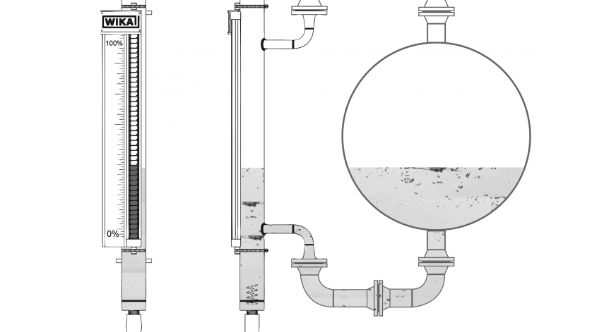
Front view (left) and side view (right) of the modified magnetic level indicator customized for a vessel with minimal available space.
Since the entire magnetic level indicator would not fit between the customer’s existing flange connections, WIKA had to get creative. By taking the normally positioned side branch connections from the magnetic level indicator chamber and adding two 90° elbows, WIKA’s experts were able to fit a longer instrument into the shorter existing piping configuration without additional work from their piping staff: The addition of the elbows made it possible to utilize existing connections and to easily install the upgraded instrument. In doing so, the connection locations allowed for a duplication of the liquid level in the magnetic level indicator chamber to the knockout pot. With this modification, the customer was able to have accurate, reliable, and safer level indication that now starts and ends where the side connections are bolted. The engineers were so pleased with the custom solution that they ordered four units.
WIKA is here to help
WIKA offers a full line of magnetic level indicators. The devices in the WMI series are robust and dependable, providing accurate level indication for many years with little or no maintenance. The WMI’s floats are built specifically for each application to supply greater accuracy. Magnet assemblies are carefully selected to minimize float and chamber size and length. Chambers are made of nonmagnetic materials such as stainless steel, Hastelloy, Inconel, and Monel, and adhere to the client’s specifications to fit perfectly within existing or new processes. The visual indicator is easy to read and comes with a ruler marked in feet/inches, meters/centimeters, or percentage, or it can be tailored to individual requirements. WMIs can be fitted with a variety of different process connections, plus vent and drain options. Other add-ons include high temperature and cryogenic insulation, steam tracing and electrical heat tracing, reinforced flange supports, and liquid gas construction.
WIKA’s experts can modify and adapt components to fit your particular needs and improve your processes. They will work with you and find a solution to your measuring issues. Give them a call today.

