Known for customized measurement solutions, WIKA recently partnered with an EPC contractor to provide orifice meter runs to be installed in a major U.S. facility that captures and utilizes carbon dioxide.
Even as global consumers and businesses increasingly adopt renewable energy, the main sources of fuel and raw materials remain petroleum and natural gas – and will continue to do so for the near future. Polymers for plastics and textiles, fertilizers, hydrogen as transportation fuel and in chemical processes – the vast majority of these important compounds have their origin in fossil fuels. In addition, natural gas deposits are the source of the helium used in aerospace applications, high-tech healthcare equipment, and the production of semiconductors.
Between now and a future when hydrocarbons are no longer extracted from the ground, carbon capture is one of the most effective and efficient technologies for reducing greenhouse gas emissions, achieving net zero, and even going carbon negative during this transition period.
What Is Carbon Capture, and How Does It Work?
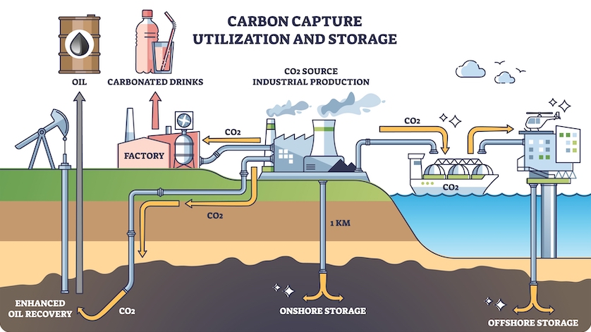
Carbon capture is the industrial process of isolating and trapping carbon dioxide before and/or after combusting fossil fuels. The captured CO2 is collected, then either stored long-term (sequestered) or utilized in another application. That’s why carbon capture (CC) is often referred to as carbon capture and storage (CCS) or carbon capture, utilization and storage/sequestration (CCUS).
Note that carbon capture is not removing carbon dioxide from the atmosphere. That process is called direct air capture, a technology that uses sorbents to filter CO2 from the air.
Technologies for Capturing, Utilizing, and Storing Carbon
There exists several effective processes for capturing carbon dioxide. The technologies are generally categorized as chemical, physical (membranes), cryogenic, or biological (vegetation).
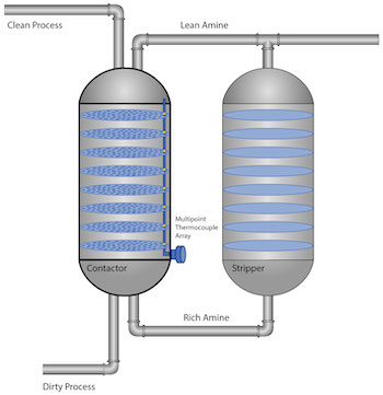
Fig. 1: Simplified diagram of an amine unit
A good example of a chemical process is the amine unit, for pre- or post-combustion carbon capture. This equipment – found in refineries, fertilizer plants, liquified natural gas (LNG) facilities, etc. – is made up of two interconnected columns (Figure 1). In the contactor column, amine solvent comes into contact with the process gas and absorbs the CO2 and sulfur compounds. The amine solution, now saturated with acid gases (rich amine), enters the stripper column, where steam removes the unwanted compounds so that the regenerated amine (lean amine) can be sent back into the contactor column to be used again. Meanwhile, the acid gases are sent to other units for further separating and refining.
Amines are also used in post-combustion carbon capture, to remove CO2 and other compounds from flue gas.
A newer technology for removing carbon dioxide is to freeze it out, available both pre-combustion and post-combustion/post-production.
- Controlled Freeze Zone™ (CFZ) is a single-step distillation process where a refrigerant cools the dirty process gas to about −50°F (−46°C), then uses controlled freezing and thawing to separate out acid gases (CO2 and H2S) from methane.
- Cryogenic CO2 capture also uses low temperature and high pressure, first drying and then cooling flue gas so that the CO2 solidifies/liquefies and separates out. Toxins like mercury and sulfur compounds are also removed. What remains is light gas, made up of mostly nitrogen (N2), which is emitted through the smokestack.
CO2 sequestration
What happens after carbon capture
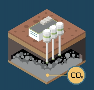
After the CO2 is removed from the dirty process or flue gas, it is compressed and then either sequestered (stored) or utilized.
Sequestration involves injecting liquefied CO2 deep underground. In geologic sequestration, the carbon enters porous rock formations through dedicated injection wells, and is trapped underground by layers of basalt. In addition, the chemicals in basalt combine with the sequestered carbon to form solid carbonates.
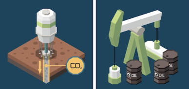
Carbon dioxide enhanced oil recovery (CO2 EOR)
CO2 isolated from dirty gases is not pure enough for making carbonated beverages, but it is useful for enhanced oil recovery (EOR). CO2 EOR is a popular method in the U.S. to pull petroleum from fields that have become unproductive using other recovery methods. Similar to carbon sequestration, EOR involves injecting liquid CO2 into porous rock strata, where it reduces the viscosity of crude oil so that it is easier to extract.
WIKA’s Meter Runs Measure Flow of Captured CO2
An international oil and gas company operates the world’s largest carbon capture facility, located in the western United States, as part of its business to extract helium and natural gas. To further reduce greenhouse gas emissions, the energy company is increasing its capabilities in CCUS. Among the equipment needed for this expansion project are flow skids, which measure and control the amount of liquid CO2 that is piped to nearby EOR sites and pumped into underground cavities.
The energy company selected a European EPC (engineering, procurement, and construction) business to supply additional flow skids for the project. When the EPC contractor needed flow meter assemblies manufactured to their precise specifications, they contacted WIKA.
A specially engineered meter run
Because no two projects are the same, the flow specialists at WIKA are accustomed to designing flow measurement solutions. This EPC customer has a long-standing relationship with WIKA and is already familiar with our ability to engineer specialized assemblies, even non-standard ones. When they asked whether we could manufacture units to their specifications, we were happy to help.
The specifics:
- Meter runs for measuring and controlling the flow of liquid CO2 under high pressure
- Location: outlet flow meter station after carbon capture
- 8-inch pipe section
- Orifice plates as the primary flow elements
- Dual-chamber orifice assembly
- Differential pressure transmitter
- Temperature transmitter with thermocouple
Dual-chamber meter run assembly
The EPC contractor requested a two-chamber orifice meter run in order to cover the entire minimum-maximum flow range for this particular application. They wanted two different sizes of orifice plates (OP) because each plate has a short range. So, when the flow rate changes to a value that is out of range for one OP, an operator can switch to the other. An added advantage of the dual-chamber design is redundancy: if one orifice plate needs to be replaced, the other one is put into service. This way, service can be done without having to halt operations and depressurize the process.
As liquid CO2 flows through each orifice plate’s two small ports, a differential pressure transmitter (DPT) connected to the ports measures the differential pressure; the instrument also measures gauge pressure. A short distance away in the meter tube is a temperature transmitter. The differential pressure transmitter takes the measured DP value, corrects it based on the flow’s pressure and temperature, and sends this compensated value as an electronic (4…20 mA) signal to a flow computer. This computer then produces the actual flow rate based on a series of signals.
We built the custom flow assemblies using the following WIKA products:
- FLC-MR meter run / meter tube
- FLC-OP orifice plate
- DPT-20 differential pressure transmitter
- xS digital temperature transmitter with HART® communication protocol
WIKA, a Trusted Partner for Custom Flow Solutions
Our product experts are known for working closely with customer and coming up with innovative instrumentation solutions that go beyond the original request. Flow measurement is a very important parameter, particularly in custody transfer systems. WIKA was able to not only provide a highly accurate flow meter assembly, but designed a system that remain online 24/7 even though orifice plate changes.
Our broad portfolio of quality instruments is always a strength when it comes to EPC projects. An additional reason this contractor partnered with WIKA was because they appreciated our innovation, flexibility, and deep knowledge of flow measurement solutions. In turn, we appreciate the role that we are able to play in reducing the level of atmospheric carbon dioxide.
Products mentioned in this article:
• FLC-MR meter run / meter tube
• FLC-OP orifice plate
• DPT-20 differential pressure transmitter
• xS digital temperature transmitter with HART® communication protocol