
In this two-part series, learn the seven factors to consider when choosing an industrial thermometer for your process’s measuring points.
The majority of measuring points in a process are used for monitoring temperature. Nowadays, these measuring points tend to be equipped with electrical temperature measurement instruments such as resistance thermometers and thermocouples. But with all the choices and options in the marketplace, which instrument is best suited for which measuring task?
There is no one-size-fits-all answer to this question. Almost every measuring point has unique criteria that must be taken into consideration. The following are some deciding factors:
1. Measuring accuracy and operating temperature
Resistance thermometers, also known as resistance temperature detectors (RTDs), provide high accuracy and excellent long-term stability. The tolerance value for class AA sensors is 0.10°C + 0.0017 | t |. However, the permissible measuring ranges for resistance sensors, according to IEC 60751, generally preclude use at temperatures higher than 600°C (1,112°F).
Although the long-term stability of thermocouples (TCs) is significantly lower than that of RTDs, apart from a few exceptions, TCs are capable of recording temperatures of up to 1,700°C (3,092°F).
2. Size and vibration resistance
Due to the size and design of their sensors, resistance thermometers have a larger diameter than thermocouples. WIKA instruments, for instance, have a minimum size of approximately 2.0 mm (0.08″) for RTDs and 0.5 mm (0.02″) for TCs.
Due to their simple construction, thermocouples are essentially unaffected by high vibrations. Standard resistance thermometers can withstand a 6 g load at the probe tip, or as much as 60 g if special designs are incorporated.
3. Response time
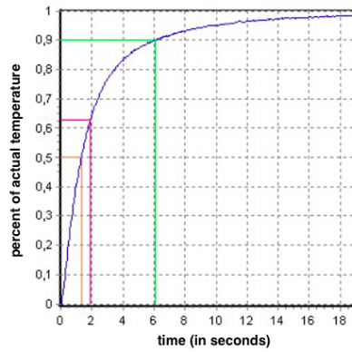
Detail of a response time diagram with three thresholds: t50 (yellow), t63 (green), and t90 (green).
The thermal response time indicates how fast an ETM instrument responds to a step change in temperature on the process side. The common benchmark of 90% time, or t90, is the time it takes for a thermometer to reach 90% of the steady-state value following a sudden temperature change.
Several factors influence the response time. Aside from the process medium and the flow velocity, the most important factor is the thermowell. The high thermal mass of this protection tube appreciably prolongs the time it takes for the medium’s heat to transfer to the temperature sensor. However, users have options to reduce this response time.
In the event of low-flow velocities, consider using thermowells with a tapered, stepped, or exposed tip. Another option is the so-called face-sensitive sensors; these are integrated in the thermowell wall and are separated from the process by only a wafer-thin diaphragm.
Improving the response time in high-flow processes is rather more complex. One possibility is to reduce the insertion depth and, hence, also the forces acting on the thermowell. However, if this means that the probe tip is no longer immersed far enough into the process, then qualified electrical temperature measurements are out of the question. Users can achieve greater stability by increasing the stem’s diameter. The downside to that, of course, is a longer response time.
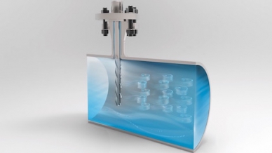
Helical strakes on a thermowell break up the vortices, rendering them too weak to cause mechanical fatigue.
Thermowells with a helical stem like WIKA’s ScrutonWell® design represent a compromise between greater strength and shorter response times. The strakes on the longer stem serve to break up the vortexes that create vibration, thereby reducing the likelihood of thermowell failure in high-velocity media.
See Part 2 of this blog for four more factors to consider when deciding which ETM instrument to use.