
Part 1 of this series covered three of the seven factors to consider when choosing the right RTD or thermocouple for a measuring point in a process. Here are the remaining four factors.
4. Ambient conditions
Like the internal process, ambient conditions often significantly impact the thermometer and the quality of its electrical temperature measurements. Intense external heat, uncompensated cable resistances, and electromagnetic fields are all factors that interfere with the signal, influencing or falsifying the measured value.
If the instrument is to be exposed to extreme cold or heat, users must be even more careful to ensure, among other things, that the design and materials are suitable for those conditions. Additionally, specific applications – e.g., hazardous areas or sterile processes – require appropriate approvals.
Thermometers soon come up against their limits in extreme ambient conditions. Due to their electronic and nonmetallic components, the operating temperature range is typically from −40°C to +85°C or +105°C (−40°F to +185°F or +221°F). Electrical temperature measurement devices must also be resistant to other environmental conditions, such as water or solid particles.
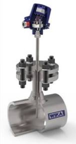
Design of a temperature measuring point and position of the signal processing electronics (transmitter)
5. Output signal
Although measurement signals, in principle, can be transmitted via a cable to the control room for further processing, external influences (see #4) impair the accuracy of electrical temperature measurements. Alternatively, a transmitter in the thermometer’s connection head generally converts the analog measurement signal locally into a standardized industrial signal that is less susceptible to failure.
Digital electronics can also expand a thermometer’s functionality and allow full configuration remotely from the control room. The most relevant and widespread technologies are 4…20 mA output signals together with the HART® protocol and various fieldbuses.
6. Installation conditions
Users must consider the physical dimensions of the complete temperature measuring point. The trend toward modular smart-scale production units creates a need for compact ETM instruments. The TR34 miniature resistance thermometer, for example, has a diameter of just 19 mm (0.78″) and a maximum height of 68 mm (2.7″), yet it can accommodate a transmitter with a 4…20 mA output.
If the measuring points are difficult to access, connecting the cable by means of individual stranded wires is likely to be a complicated affair. Thermometers with a connection head have a cable gland at the inlet, which protects the device against particles, dust, and water. Process adapters like the M12 plug simplify the electrical connection.
Measuring points with an in situ display in the housing of the connection head are recommended for small, autonomous systems or for units where the temperature sensors are not connected to a control room. If the mounting position results in poor readability, a remote display can be attached as well.
7. Approvals
Lastly, end users must consider the country in which the measuring instrument will be located and what approvals may be required. While some regions have lax certification standards, others are very strict about specific approvals.
As a global company, WIKA is your ideal partner for making sure your resistance thermometers and thermocouples are certified for use around the world. We also offer expert advice on a comprehensive portfolio of products for electrical temperature measurement, including transmitters, switches, thermowells, programming units, and other accessories. Contact us for more information on ETM solutions that are customized for your particular applications.