
When installing thermowells in a pipeline, a user must first answer several questions regarding their location, quantity, stem length, distance from each another, and effects on the process media.
Thermowells are highly effective devices for protecting temperature sensors, such as resistance thermometers (RTDs), from process media in a pipeline. They are usually inserted perpendicular to the flow, using a flange connection. However, there’s an art to thermowell placement and installation. Some of the most common questions I’ve received:
- What is the ideal insertion length for a thermowell?
- How far apart should thermowells be from each other?
- Where in relation to an elbow should the thermowell be installed?
Here are some answers about thermowell selection, placement, and installation.
1. Insertion length for a thermowell
The right length for a thermowell largely depends on the diameter of the pipe or tube. One rule of thumb is to insert a thermowell anywhere from one-third to two-thirds of the way into the fluid stream. Other guidelines recommend that the insertion length be 10 times the thermowell tip diameter or a minimum of 2 inches (50mm) into the process.
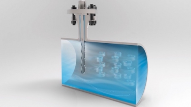
Helical strakes on a thermowell break up the vortices, rendering them too weak to cause mechanical fatigue.
The goal is to balance the potential for mechanical failure and the potential for sensing error. On the one hand, the longer the insertion length, the greater the chances that the thermowell will bend or suffer mechanical fatigue due to the process media’s velocity. On the other hand, the shorter the insertion length, the greater the chances that users will see unreliable results due to poorer heat transfer. In summary, there is not one perfect stem length for a thermowell, but a goal of balancing outcomes.
One way to reduce vibration and mechanical fatigue is to use a thermowell with a ScrutonWell® design, which has helical strakes to suppress vortex-induced vibrations. Rigorous endurance tests have prove the effectiveness of the ScrutonWell® Design as a vortex breaker.
2. Multiple thermowell installations
Most of the time, one thermowell with a temperature sensor is sufficient for a section of pipe. However, some processes call for multiple thermowells in an area. The key when installing several thermowells is to minimize their influence on one another while providing a consistent flow character in the process. There are two ways to do this:
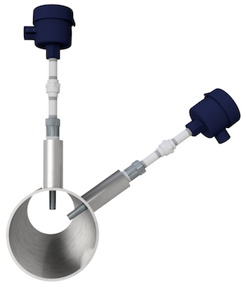
Thermowells installed at offset angles
Offset angles – In this scenario, both thermowells are installed at the same location but at angled offsets from each other. By having them at the same location, they are not influenced upstream or downstream from an inline installation. They should be installed at a minimum angular offset to allow for easy installation and removal. Also, the thermowell tips should be far enough away from each other so as to not influence each other’s readings.
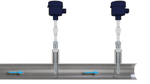
Thermowells installed inline
Inline – To ensure laminar flow in the process, the distance between thermowells can vary from 10 to 100 times the pipe diameter, a wide range indeed! Several factors go into how far apart inline thermowells should be placed, but a conservative estimate is 25 times the pipe size. For example, in a pipeline with a 4-inch (100mm) diameter, the distance between thermowell installations is about 8 feet (2.5m): 4″ x 25 = 100″ = 8.33′.
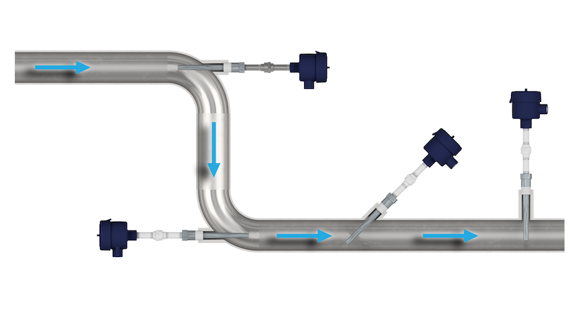
3. Elbow installations
The installation in an elbow allows the sensing area of the thermowell to be placed in the centerline of the pipe, ensuring an optimal location for measuring the process’s temperature. There are two different sites of thermowell installations in an elbow:
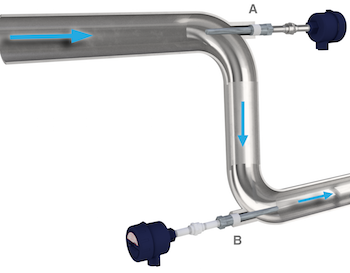
Thermowell installations in elbows: A. facing upstream, B. facing downstream
Facing upstream – The thermowell tip (temperature sensing area) is upstream of any influence, such as mixing or swirling, of the elbow. Many users prefer this elbow installation over “facing downstream” (see next bullet), although the bending moment calculations to ASME PTC 19.3 TW-2016 are outside the scope of this standard.
Facing downstream – The thermowell tip is downstream of the elbow, which means that it can be influenced by any mixing or swirling that the elbow causes. The advantage when performing thermowell wake frequency calculations is that facing downstream takes a conservative approach and assumes it is a perpendicular installation.
Other considerations for thermowell installation
Thermowell length, distance apart, and location are the main considerations when installing these protective fittings, but they are not the only ones. Users should also keep in mind these other factors:
- Pipe size – ranging from small (2″ to 4″) to large (> 60″)
- Process media – whether it’s gas or liquid
- Two-phase flow – such as gas and liquid, two different liquids, a liquid and solid particles, or a gas and solid particles
- Type of flow – steady or pulsating
- Distance from other measuring instruments or fittings
Many factors go into choosing the correct type, size, and location for a thermowell. For more information about which fitting is right your particular process and requirements, or where a thermowell should be installed in a pipeline, contact the temperature measurement specialists at WIKA USA.
I need some technical white papers for understanding How far apart should thermowells be from each other?
Hey Panduranga,
You question is answered within the blog. Check out section 2. Multiple thermowell installations. Hope this helps!
Faith
When installing an R-Type thermowell (porcelain) through castable refractory, what is the best practice for installation? I’ve seen castable refractory placed against the thermowell which causes damage when needing to be removed for replacement. Should thermowell be installed before the castable refractory is installed?
Generally the Ceramic style thermowell is installed after the castable refractory is installed. Care should be taken to ensure adequate clearance between thermowell and insertion hole. Additional points to consider would be refractory shifting, insertion length into the refractory, any debris hitting/damaging the thermowell, if installation is during operations/shutdown etc. We have a general operating instruction that can be referenced for our TC80 product. Refer to section 5 or page 10 for information on commissioning the product.
https://www.wika.com/media/Operating-instructions/Operating-instructions/Temperature/Thermocouples/oi_tc80_tc82_tc83_tc84_en_de.pdf
If you would like any additional information please let me know.
Kind Regards,
Adam DeLancey
Generally, we do have a thermowell of 6 inches & 8 inches in size. Can we install 6 inch thermowell in an one inch dia. pipeline? is there any limitation to the pipe size for thermowell installation?
The length of thermowell is dependent on the process connection to the piping and the ID of the process pipe that it is installed into to determine the details of the thermowell (insertion length, tip diameter, root diameter, bore diameter etc.). With the pipeline diameter being one inch in diameter you should size a thermowell with process connection to fit appropriately inside and not completely restrict the flow.
Dear Mr. DeLancey,
could you please let me know if WIKA can provide a verifcation of a tube-array (typically nr. 4-off TWs installed on a circular pipe, in the following configuration :
nr. 2 TWs (offset angle installation), upstream
nr. 2 TWs (offset angle installation), downstream to the first nr. 2 TWs
Do you have any reference study and / or literature ?
Thank you so much,
Paolo (PMB ITALIA, Italy)
Hi Paolo,
Your request has been transferred to WIKA Italy They should be reaching out to you soon and they should be able to help you out.
Hi Paolo,
The ASME PTC 19.3 TW-2016 mentions in 6-3.4 Flow-Induced Vibration of Thermowell Arrays. It’s possible to evaluate the results of the standard to ASME N-1300 as a special engineered solution. By 9-1, the full responsibility of the intended installation rests with the designer of the system that incorporates the thermowell. We do have some thermowell software, but no literature for your specific question. If you have any other questions please let us know.
Could you help to mention source of length of immerison thermowell standard refer to which international standard ? And how standard for liquid & gas ?
Hello Adhit, I would refer to API RP 551 – Section Thermowells.