
Flow tests by the National Engineering Laboratory in Glasgow confirm that thermowells with a ScrutonWell® design suppress vortex-induced vibrations, a benefit especially for oil and gas pipelines with higher flow rates and small nozzle connections.
Industrial chimneys with helical strakes stand firm, no matter how strong the winds. Numerous experiments, not to mention real-life situations, have proven time and time again the effectiveness of a design patented by Christopher Scruton and Denis E. J. Walshe in 1957: that helical strakes on the external surface of a “bluff elongated cantilever-supported body of generally regular geometrical shape” will stabilize a wind-excited structure.
But does the same principle hold true for other long and thin bodies? Some people have their doubts. As far as thermowells are concerned, however, a recent endurance test commissioned by WIKA has confirmed what has already been demonstrated in thousands of actual applications.
Why vortexes form, and how to break them
Under rapid-flow conditions, two rows of vortices – each rotating in an opposite direction – form behind a thermowell. This phenomenon is called a Kármán vortex street. When they detach, these vortices create periodic lift and drag forces that could cause the thermowell to vibrate and eventually fail due to mechanical fatigue.
However, when the thermowell has helical strakes, this design breaks up the vortices, rendering them weak and ineffective. In short, a helical design suppresses vortex-induced vibrations (VIV) and rules out the risk of failure due to dynamic fatigue.
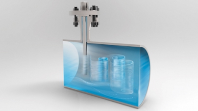
A wake forms behind a smooth thermowell, generating large vortices that can cause mechanical fatigue.
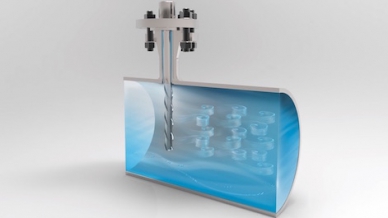
Helical strakes on a thermowell break up the vortices, rendering them too weak to cause mechanical fatigue.
Testing WIKA’s ScrutonWell® design: Methodology
In early 2018, WIKA commissioned a behavioral comparison of a thermowell with a ScrutonWell® design against a standard thermowell at the flow testing facility of the internationally renowned TUV SUD NEL(National Engineering Laboratory) in Glasgow. The test comprised 47 experimental runs in a pipe containing gasoil. This diesel-like medium flowed over the thermowell at room temperature and at a velocity of between 0.5 m/s and 6 m/s.

NEL’s flow testing facility
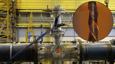
ScrutonWell® stem mounted in the pipe
To measure the dynamic load at the transition to the flange, both thermowells were equipped with strain gauges for the duration of the test series. An accelerometer in the thermowell bore served to record the velocity values at the thermowell tip. All tests were documented using a high-speed camera that provided up to 12,500 frames per second.
Prior to commencing the tests, the dimensions of the standard thermowell were adapted according to ASME PTC 19.3 TW-2016, the calculation standard, to ensure that vibration would in fact occur in the tested velocity range – both in the flow direction (in-line resonance) and at right angles to it (transverse resonance). The model TW10-F thermowell in ScrutonWell® designwas designed with the same dimensions for comparison testing. The natural frequency of this thermowell was calculated as 38.7 Hz; in other words, it deviated by only 4.1% from the frequency determined at NEL by means of experiments. This result testifies to the high reliability of the WIKA thermowell calculation software.
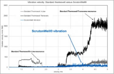
Fig. 1: Comparison of vibration velocity at the two thermowell tips
Results of the endurance tests
In Figure 1, we see that the maximum vibration measured at the tip of the standard thermowell was approximately 4.5 m/s rms at a flow velocity of around 1.8 m/s (in-line resonance, in gray) and approximately 2,480 mm/s rms at a velocity of around 5 m/s (transverse resonance, in black). No comparable maximum values were determined for the ScrutonWell® design (in blue). Vibration in the ScrutonWell® design increased linearly with the flow but remained very low. Strain gauge measurements of the dynamic stress at the thermowell root produced a similar picture.
Thanks to the high-speed camera, it was possible to measure the vibration amplitudes with extreme accuracy. Taking the transverse resonance for a 4.5 m/s flow as an example, Figure 2 documents the standard thermowell as having a deflection of 27 mm. The ScrutonWell® thermowell exhibits a deflection of just 1.2 mm – about 96% less – under identical conditions (Figure 3).
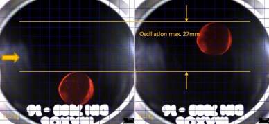
Figure 2*: Deflection of the standard thermowell at 4.5 m/s
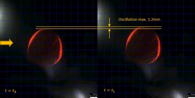
Figure 3*: Deflection of the ScrutonWell® thermowell at 4.5 m/s
* The dark background is due to the fact that gasoil, which is transparent with an amber color when at rest, becomes almost opaque when flowing.
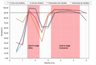
Figure 4: Vibration damping with the ScrutonWell® design
Damping ratio (ζ)
The damping of the ScrutonWell® design was demonstrated in comparison to the standard thermowell in 47 experimental runs with several tens of thousands of measurements. A factor ζ = (1- v ScrutonWell® / v standard-thermowell) was introduced to enable this damping to be quantified. A damping factor of ζ > 0 would identify the ScrutonWell® as superior. A ζ < 0 value would make the standard thermowell the winner of the design comparison.
The test proved that the mean damping of the ScrutonWell® thermowell in the in-line resonance range is 90.9% of that for the standard thermowell design (Figure 4). A mean damping of 92.8% was recorded in the transverse resonance range. However, since the measured values exceeded the instrument measuring ranges in almost all of the transverse resonance tests, it can be assumed that the damping of the ScrutonWell® design is actually much higher.
Measuring temperature response times
In addition to measuring vibrations at NEL, WIKA conducted a follow-up test of temperature response times to show that the ScrutonWell® design does not adversely affect a thermowell’s performance. These times were measured in a water–glycol mixture in accordance with ASTM E644-09, the test standard for resistance thermometers. The temperature change at the two thermowells was measured at an immersion depth of 150 mm. As Figure 5 shows, the ScrutonWell® design had a 17.6% faster response time compared to the standard thermowell (T90-time).
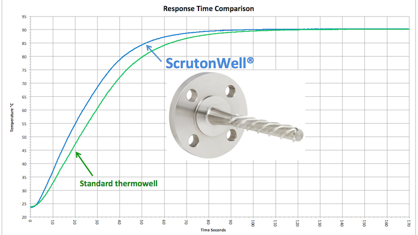
Figure 5: Comparison of response times of a standard thermowell vs. the ScrutonWell® design
Conclusion: ScrutonWell® design delivers what it promises
These latest tests by NEL follow initial tests conducted at the Institute of Mechanics and Fluid Dynamics at TU Bergakademie Freiberg (Freiberg University of Mining and Technology) in 2014. Both confirm that thermowells with a ScrutonWell® design live up to every expectation. Thermowells with helical strakes are a good solution whenever other options for passing calculations using the ASME PTC 19.3 TW-2016 standard are problematic.
Very short or thick-walled thermowells may well meet the ASME requirements for mechanical strength. However, response times and precision tend to be poor. The need to strictly observe the flange nozzle dimensions (“interference fit”) and the thermowell’s mounting position only complicates matters further. If the thermowell has to be supported by a collar, mounting is expensive and requires considerable time and effort.
In all such situations, thermowells with a ScrutonWell® design are an attractive alternative, as confirmed by numerous tests. The helical design unites the benefits of extremely effective VIV suppression with the hassle-free mounting of a standard thermowell – all without adversely affecting response times in temperature measurement.