A butter-pad allows refineries to weld new thermocouples onto it rather than directly on the bare furnace tube, as repeated welding damages the tube’s integrity. However, using this weld overlay affects the accuracy of temperature readings. WIKA conducted a series of IR scans, CFD simulations, and tests to quantify the temperature deviations caused by using a butter-pad with tubeskin thermocouples.
Temperature monitoring is essential to the efficient operation of fired heaters. Accurate temperature readings allow refineries to operate with furnace tubes very close to the creep, and to minimize fouling and coking inside those tubes.
The most efficient way to get accurate temperature readings of furnace tubes is with surface thermocouples, which have advantages over pyrometers. Through extensive testing, WIKA’s R&D Center has verified that the readings of tubeskin thermocouples are true representations of actual tube metal temperature as measured by installed reference thermocouples.
Tubeskin Thermocouples, Welding Issues, and Butter-Pads
Thermocouples are accurate, long-lasting temperature sensors. However, because tubeskin thermocouples (TSTCs) are subjected to extreme temperatures, their reliability is limited to a few turnaround cycles, after which they should be replaced. Herein lies the problem:
- TSTCs are typically welded onto the tube surface.
- Replacement TSTCs need to be installed near the failed TSTCs’ existing location.
- The metallurgy of certain tubes does not allow for welding after extended use.
Therefore, refineries are limited in their ability to weld new thermocouples directly onto bare tubes when old thermocouples fail.
One of the ways to overcome the furnace tube’s metallurgical limitations is with a butter-pad. This is a predefined thickness of weld material installed on the tube surface. The new TSTC is then mounted on this weld overlay rather than on the bare tube, thereby avoiding any issues with tube integrity or requiring extensive post-weld heat treatment (PWHT).
However, using a butter-pad has its own issues. We wanted to understand how much this extra layer of metal impacted temperature measurement accuracy.
Methodology: Testing the accuracy of TSTCs installed on a butter-pad
WIKA has a R&D Center in Houston with a 9.6M BTU fired heater that can replicate a variety of process conditions. This test unit allows us to determine the accuracy of TSTCs installed on butter-pads.
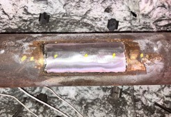
Radially (longitudinal) installed butter-pad
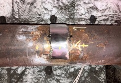
Circumferentially (transversal) installed butter-pad
The variables of this project:
- Weld material of a fixed dimension and thickness, installed circumferentially (transversal) or radially (longitudinal)
- Different emissivity values of the butter-pad
- Thermocouples products installed on bare tube vs. butter-pad
- Different operating conditions
Reference thermocouples
As a reference, we installed tested thermocouples with known accuracies. Peening is one of the most common ways to install reference TSTCs, as this gives the truest tube skin temperatures. However, the number of tests that we had planned would require many changeouts and drill holes, making this method infeasible.
One alternative to the peened-in method is the capacitance discharge method for attaching reference thermometers to the surface. We tested this alternative method by comparing its temperature readings to those of a peened-in thermocouple, and found that the average temperature deviation between the two to be ~1.1°F (0.5°C) under various firing and process conditions. As this deviation is small, we felt confident in using the capacitance discharge method to weld reference thermocouples to the butter-pad. Note: The fired heater at the WIKA R&D Center is repeatable within 1°F (0.5°C), based on the many benchmarking and profiling tests carried out on this unit.
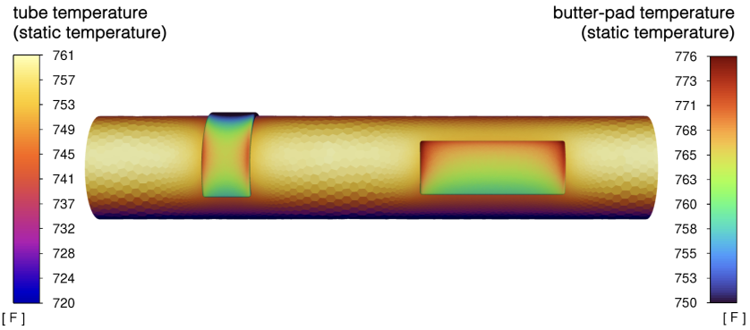
Fig. 1: Transversal (left) and longitudinal butter-pad on furnace tubeskin, IR thermography (click to enlarge)
Test results: Butter-pad on bare tube
Before testing TSTCs installed on a butter-pad, we first needed to understand the temperature distribution of the butter-pads themselves. Using infrared (IR) scanning, we found that the temperature at the weld overlay surface is consistently about 4°F (2.2°C) higher than the bare tube (see Figure 1). Results from computational fluid dynamics (CFD) simulations matched closely with the test data (see Table 1).
Table 1: Temperature of bare tube vs. butter-pad, IR thermography and CFD simulation
No. | Firing | Reference (bare tube) | Butter-pad (IR) | Butter-pad (CFD) |
1 | 6.9 | 762°F | 766°F | 765°F |
2 | 5.9 | 735°F | 738°F | 737°F |
3 | 4.6 | 700°F | 704°F | 702°F |
The butter-pad surface temperature was lower than expected for a metal with a 0.196″ (5mm) thickness. IR scanning revealed an emissivity value of 0.67 to match the temperature, and this was further validated with the CFD model of the setup. The CFD was run again, this time with an emissivity of 0.45 and 0.85, both at the maximum firing rate, to understand the impact of emissivity on the surface temperature.
As expected, when the butter-pad is more polished than the bare tube, its lower emissivity value resulted in a cooler surface temperature. The inverse is true: a less polished surface (higher emissivity value) resulted in a hotter surface temperature (see Table 2).
Table 2: Butter-pad temperature with varying emissivity values, CFD simulation
No. | Butter-pad | Butter-pad | Butter-pad |
1 | 0.45 | 735°F | −27°F |
2 | 0.67 | 764°F | +3°F |
3 | 0.85 | 785°F | +23°F |
* at the center
We found it interesting that the butter-pad’s temperature was not consistent across its surface. Rather, the temperature tended to be higher at the edges and cooler toward the center (see Figure 2).
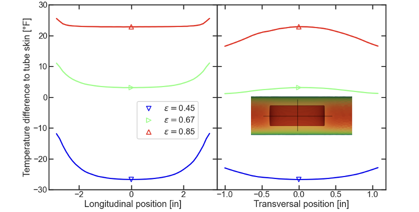
Fig. 2: Butter-pad temperatures with varying orientations and emissivity values, CFD simulation
| Longitudinal variation with ε | Transversal variation with ε |
|
|
The last CFD simulation we did was to understand the impact of hotter firing conditions on the butter-pad temperature as compared to the bare surface temperature (see Table 3).
Table 3: Bare tube vs. butter-pad temperatures at different firings, CFD simulation
No. | Firing (MMBtu/hr) | Bare tube | Butter-pad |
1 | 6.9 [normal heat] | 798°F | 801°F |
2 | 12.7 [high heat] | 1,000°F | 1,003°F |
The validated CFD model was used to simulate test-run conditions for which product test data are available for bare tube installation.
Test results: Thermocouple installed on butter-pad
After analyzing and validating the above data, we then ran simulations and actual tests on the performance of our thermocouple product welded on top of the butter-pad. Doing so helped us understand the butter-pad’s impact on sensor accuracy. The MMBtu/hour test points were kept the same to maintain a similar basis for comparison.
First, we tested the product, unshielded and shielded, on a bare tube (see Table 4).
Table 4: Temperature deviation of unshielded vs. unshielded TSTC on bare tube
No. | Firing | Bare tube temperature | Temperature reading | Temperature deviation | |
1 | 6.9 | 797°F | unshielded TSTC | 800°F | +3°F |
shielded TSTC | 796°F | −1°F | |||
2 | 12.7 | 1,001°F | unshielded TSTC | 1,004°F | +3°F |
shielded TSTC | 992°F | −9°F |
The data show that both the unshielded and shielded sensors are accurate within the thermocouples’ standard limits of error (SLE) tolerance for both normal and high heat release.
Second, we tested the product, unshielded and shielded, installed on a butter-pad (see Table 5).
Table 5: Temperature deviation of unshielded vs. unshielded TSTC on butter-pad
No. | Firing | Bare tube temperature | Temperature reading | Temperature deviation | |
1 | 6.9 | 797°F | unshielded TSTC | 817°F | +20°F |
shielded TSTC | 819°F | +22°F | |||
2 | 12.7 | 1,001°F | unshielded TSTC | 1,027°F | +26°F |
shielded TSTC | 1,022°F | +21°F |
Judging by the data, both the unshielded and shielded product read higher by ≥20°F when installed on a butter-pad vs. on a bare tube. It is worth mentioning that the particular products used in these tests are highly accurate when installed on bare tubes; thermocouples that are less accurate would see an even greater temperature deviation, depending on their design.
This article continues with “Tubeskin Temperature Measurement: How to Improve Tubeskin Thermocouple Accuracy on a Butter-Pad.”